BlackBerry 10: Type, swipe a word

WorldWide Tech Science. BlackBerry 10: Type, swipe a word and don`t look back for space. Video.RIM has posted a video on youtube to explain the advantages of its BB10 keyboard, you can type, swipe a suggested word. You also don`t need to worry about a missing space between the words you are...

This is default featured post 2 title

Go to Blogger edit html and find these sentences.Now replace these sentences with your own descriptions.This theme is Bloggerized by Lasantha Bandara - Premiumbloggertemplates.com.

Wednesday, December 29, 2010

555 TIMERS MADE EASY

Learning

The 555 timer is a simple integrated circuit that can be used to make many different electronic circuits. With this information you will learn how how the 555 works and will have the experience to build some of the circuits below.

An Overview of the 555 Timer

The 555 Integrated Circuit (IC) is an easy to use timer that has many applications. It is widely used in electronic circuits and this popularity means it is also very cheap to purchase, typically costing around 30p. A 'dual' version called the 556 is also available which includes two independent 555 ICs in one package.

The following illustration shows both the 555 (8-pin) and the 556 (14-pin).
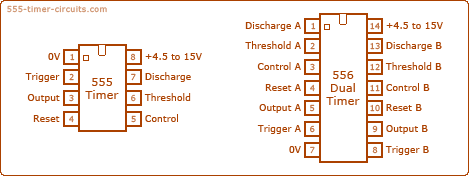
555 and 556 Timer

In a circuit diagram the 555 timer chip is often drawn like the illustration below. Notice how the pins are not in the same order as the actual chip, this is because it is much easier to recognize the function of each pin, and makes drawing circuit diagrams much easier.
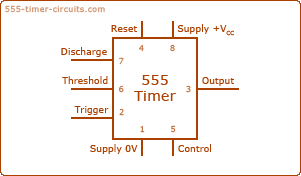
555 Timer Symbol

For the 555 to function it relies on both analogue and digital electronic techniques, but if we consider its output only, it can be thought of as a digital device. The output can be in one of two states at any time, the first state is the 'low' state, which is 0v. The second state is the 'high' state, which is the voltage Vs (The voltage of your power supply which can be anything from 4.5 to 15v. 18v absolute maximum). The most common types of outputs can be categorized by the following (their names give you a clue as to their functions):

  • Monostable mode: in this mode, the 555 functions as a "one-shot". Applications include timers, missing pulse detection, bouncefree switches, touch switches, frequency divider, capacitance measurement, pulse-width modulation (PWM) etc
  • Astable - free running mode: the 555 can operate as an oscillator. Uses include LED and lamp flashers, pulse generation, logic clocks, tone generation, security alarms, pulse position modulation, etc.
  • Bistable mode or Schmitt trigger: the 555 can operate as a flip-flop, if the DIS pin is not connected and no capacitor is used. Uses include bouncefree latched switches, etc.

    Pin Configuration of the 555 Timer

    Here is the identification for each pin:
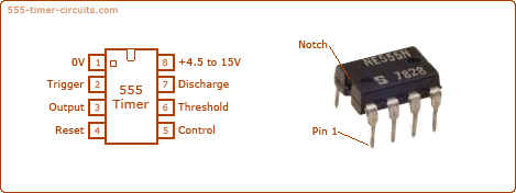

    When drawing a circuit diagram, always draw the 555 as a building block, as shown below with the pins in the following locations. This will help you instantly recognise the function of each pin:


    Pin 1 (Ground):
    Connects to the 0v power supply.

    Pin 2 (Trigger):
    Detects 1/3 of rail voltage to make output HIGH. Pin 2 has control over pin 6. If pin 2 is LOW, and pin 6 LOW, output goes and stays HIGH. If pin 6 HIGH, and pin 2 goes LOW, output goes LOW while pin 2 LOW. This pin has a very high impedance (about 10M) and will trigger with about 1uA.

    Pin 3 (Output):
    (Pins 3 and 7 are "in phase.") Goes HIGH (about 2v less than rail) and LOW (about 0.5v less than 0v) and will deliver up to 200mA.

    Pin 4 (Reset):
    Internally connected HIGH via 100k. Must be taken below 0.8v to reset the chip.

    Pin 5 (Control):
    A voltage applied to this pin will vary the timing of the RC network (quite considerably).

    Pin 6 (Threshold):
    Detects 2/3 of rail voltage to make output LOW only if pin 2 is HIGH. This pin has a very high impedance (about 10M) and will trigger with about 0.2uA.

    Pin 7 (Discharge):
    Goes LOW when pin 6 detects 2/3 rail voltage but pin 2 must be HIGH. If pin 2 is HIGH, pin 6 can be HIGH or LOW and pin 7 remains LOW. Goes OPEN (HIGH) and stays HIGH when pin 2 detects 1/3 rail voltage (even as a LOW pulse) when pin 6 is LOW. (Pins 7 and 3 are "in phase.") Pin 7 is equal to pin 3 but pin 7 does not go high - it goes OPEN. But it goes LOW and will sink about 200mA.

    Pin 8 (Supply):
    Connects to the positive power supply (Vs). This can be any voltage between 4.5V and 15V DC, but is commonly 5V DC when working with digital ICs.

    Inside the 555 Timer

    You may wonder what is inside the 555 timer chip or what makes it work. Well, the 555 timer chip an Intergrated Circuit (IC) and therefore it contains a miniturized circuit surrounded by silicon. Each of the pins is connected to the circuit which consists of over 20 transistors, 2 diodes and 15 resistors.

    The illustration below shows the functional block diagram of the 555 timer IC.
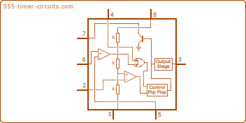
    Inside the 555 Timer Chip

    Do you notice the three 5k resistors? This is how the chip got it's name.


    555 Timer Operating Modes

    The 555 has three main operating modes, Monostable, Astable, and Bistable. Each mode represents a different type of circuit that has a particular output.

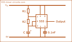
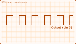
    Astable mode

    An astable circuit has no stable state - hence the name "astable". The output continually switches state between high and low without without any intervention from the user, called a 'square' wave. This type of circuit could be used to give a mechanism intermittent motion by switching a motor on and off at regular intervals. It can also be used to flash lamps and LEDs, and is useful as a 'clock' pulse for other digital ICs and circuits.

    Monostable mode

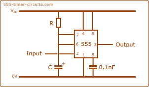
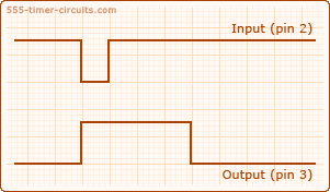
    A monostable circuit produces one pulse of a set length in response to a trigger input such as a push button. The output of the circuit stays in the low state until there is a trigger input, hence the name "monostable" meaning "one stable state". his type of circuit is ideal for use in a "push to operate" system for a model displayed at exhibitions. A visitor can push a button to start a model's mechanism moving, and the mechanism will automatically switch off after a set time.

    Bistable Mode (or Schmitt Trigger)

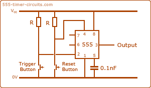
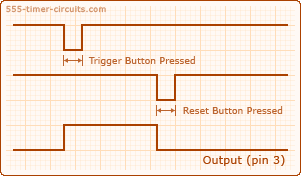
    A bistable mode or what is sometimes called a Schmitt Trigger, has two stable states, high and low. Taking the Trigger input low makes the output of the circuit go into the high state. Taking the Reset input low makes the output of the circuit go into the low state. This type of circuit is ideal for use in an automated model railway system where the train is required to run back and forth over the same piece of track. A push button (or reed switch with a magnet on the underside of the train) would be placed at each end of the track so that when one is hit by the train, it will either trigger or reset the bistable. The output of the 555 would control a DPDT relay which would be wired as a reversing switch to reverse the direction of current to the track, thereby reversing the direction of the train.

    Using the Output of a 555 Timer

    The output (Pin 3) of the 555 can be in one of two states at any time, which means it is a digital output. It can be connected directly to the inputs of other digital ICs, or it can control other devices with the help of a few extra components. The first state is the 'low' state, which is the voltage 0V at the power supply. The second state is the 'high' state, which is the voltage Vcc at the power supply.

    Sinking and Sourcing

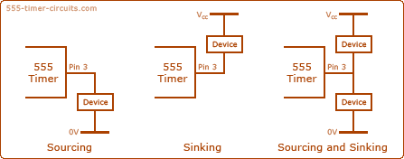
    When the Output goes low, current will flow through the device and switch it on. This is called 'sinking' current because the current is sourced from Vs and flows through the device and the 555 to 0V.

    When the Output goes high, current will flow through the device and switch it on. This is called 'sourcing' current because the current is sourced from the 555 and flows through the device to 0V.

    Sinking and sourcing can also be used together so that two devices can be alternately switched on and off.
    Sinking and Sourcing a 555 Timer

    The device(s) could be anything that can be switched on and off, such as LEDs, lamps, relays, motors or electromagnets. Unfortunately, these devices have to be connected to the Output in different ways because the Output of the 555 can only source or sink a current of up to 200mA. Make sure your power supply can provide enough current for both the device and the 555, otherwise the timing of the 555 will be affected.


    Common Mistakes When Using a 555 Timer

    Here are some mistakes to avoid:

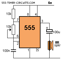
    1. Pin 7 gets connected to the 0v rail via a transistor inside the chip during part of the operation of the 555. If the pot is turned to very low resistance in the following circuit, a high current will flow through the pot and it will be damaged:


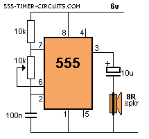
    2. The impedance of the 100u electrolytic will allow a very high current to flow and the chip will get very hot. Use 10u maximum when using 8R speaker.


    3. The reset pin (pin 4) is internally tied HIGH via approx 100k but it should not be left floating as stray pulses may reset the chip.


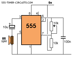
    4. Do not draw 555 circuits as shown in the following diagram. Keep to a standard layout so the circuit is easy to follow.


    5. Here's an example from the web. It takes a lot of time to work out what the circuit is doing:
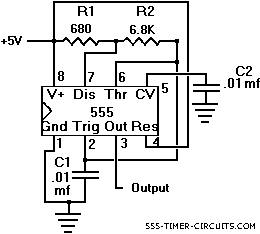


    The aim it to lay-out a circuit so that it shows instantly what is happening. That's why everything must be in recognised locations.

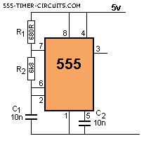
    Here is the corrected circuit: From this diagram it is obvious the circuit is an oscillator (and not a one-shot etc).


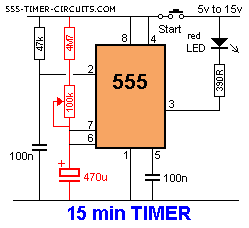
    6. Don't use high value electrolytics and high resistances to produce long delays. The 555 is very unreliable with timing values above 5-10 minutes. The reason is simple. The charging current for the electrolytic is between 1 - 3 microamp in the following diagram (when the electro is beginning to charge) and drops to less than 1 microamp when the electro is nearly charged.
    If the leakage of the electro is 1 microamp, it will never fully charge and allow the 555 to "time-out."


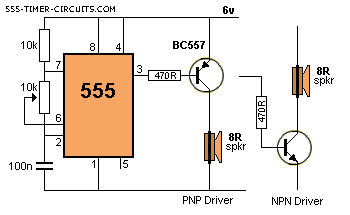
    7. Do not connect a PNP to the output of a 555 as shown in the following diagram. Pin 3 does not rise high enough to turn off the transistor and the current taken by the circuit will be excessive. Use an NPN driver.
SOURCE:

http://www.555-timer-circuits.com

Thursday, December 23, 2010

IC MAX232 FOR INTERFACING COMPUTER USING RS-232 WITH EXTERNAL HARDWARE(�c or �p)


From my previous article RS232 SERIAL COMMUNICATION STANDARD ,we know that RS232 serial is used to communicate external hardware like microprocessors and micro controllers with computer
Serial RS-232 communication works with voltages (between -15V ... -3V are used to transmit a binary '1' and +3V ... +15V to transmit a binary '0') . On the other hand, external interfacing hardware like microprocessors and microcontrollers of modern VLSI technology are made of TTL logic operates between 0V ... +5V (roughly 0V ... +0.8V referred to as low for binary '0', +2V ... +5V for high binary '1' ). Modern low-power logic operates in the range of 0V ... +3.3V or even lower.

So, the maximum RS-232 signal levels are far too high for today's TTL logic electronic hardwares, and the negative

RS-232 voltage can't be grokked at all by the TTL logic. Therefore, to receive serial data from an RS-232 interface the voltage has to be reduced, and the 0 and 1voltage levels inverted. In the other direction (sending data from some logic over RS-232) the low logic voltage has to be "bumped up", and a negative voltage has to be generated, too.

All this can be done with conventional analog electronics, e.g. a particular power supply and a couple of transistors or the once popular 1488 (transmitter) and 1489 (receiver) ICs. However, since more than a decade it has become standard in amateur electronics to do the necessary signal level conversion with an integrated circuit (IC) from the MAX232 family (typically a MAX232A or some clone). In fact, it is hard to find some RS-232 circuitry in amateur electronics without a MAX232A or some clone.

It should be noted that the MAX232(A) is just a driver/receiver. It does not generate the necessary RS-232 sequence of marks and spaces with the right timing, it does not decode the RS-232 signal, it does not provide a serial/parallel conversion. All it does is to convert signal voltage levels. Generating serial data with the right timing and decoding serial data has to be done by additional circuitry, e.g. by a 16550 UART or one of these small micro controllers (e.g. Atmel AVR, Microchip PIC) getting more and more popular.

The original manufacturer (and now some clone manufacturers, too) offers a large series of similar ICs, with different numbers of receivers and drivers, voltages, built-in or external capacitors, etc. E.g. The MAX232 and MAX232A need external capacitors for the internal voltage pump, while the MAX233 has these capacitors built-in. The MAX233 is also between three and ten times more expensive in electronic shops than the MAX232A because of its internal capacitors. It is also more difficult to get the MAX233 than the garden variety MAX232A.

A similar IC, the MAX3232 is nowadays available for low-power 3V logic.

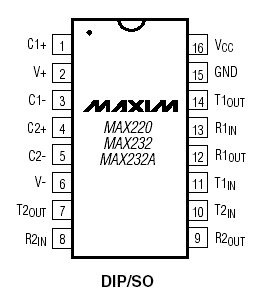
MAX232(A) DIP Package

MAX232 Maxim IC
MAX232(A) DIP Package Pin Layout
NbrNamePurposeSignal VoltageCapacitor Value MAX232Capacitor Value MAX232A
1C1++ connector for capacitor C1capacitor should stand at least 16V1�F100nF
2V+output of voltage pump+10V, capacitor should stand at least 16V1�F to VCC100nF to VCC
3C1-- connector for capacitor C1capacitor should stand at least 16V1�F100nF
4C2++ connector for capacitor C2capacitor should stand at least 16V1�F100nF
5C2-- connector for capacitor C2capacitor should stand at least 16V1�F100nF
6V-output of voltage pump / inverter-10V, capacitor should stand at least 16V1�F to GND100nF to GND
7T2outDriver 2 outputRS-232
8R2inReceiver 2 inputRS-232
9R2outReceiver 2 outputTTL
10T2inDriver 2 inputTTL
11T1inDriver 1 inputTTL
12R1outReceiver 1 outputTTL
13R1inReceiver 1 inputRS-232
14T1outDriver 1 outputRS-232
15GNDGround0V1�F to VCC100nF to VCC
16VCCPower supply+5Vsee abovesee above

V+(2) is also connected to VCC via a capacitor (C3). V-(6) is connected to GND via a capacitor (C4). And GND(15) and VCC(16) are also connected by a capacitor (C5), as close as possible to the pins.

EQUIVALENT IC DIAGRAM:

MAX232 circuit diagram


A Typical Application

The MAX232(A) has two receivers (converts from RS-232 to TTL voltage levels) and two drivers (converts from TTL logic to RS-232 voltage levels). This means only two of the RS-232 signals can be converted in each direction. The old MC1488/1498 combo provided four drivers and receivers.

Typically a pair of a driver/receiver of the MAX232 is used for

  • TX and RX

and the second one for

  • CTS and RTS.

There are not enough drivers/receivers in the MAX232 to also connect the DTR, DSR, and DCD signals. Usually these signals can be omitted when e.g. communicating with a PC's serial interface. If the DTE really requires these signals either a second MAX232 is needed, or some other IC from the MAX232 family can be used (if it can be found in consumer electronic shops at all). An alternative for DTR/DSR is also given below.

Maxim's data sheet explains the MAX232 family in great detail, including the pin configuration and how to connect such an IC to external circuitry. This information can be used as-is in own design to get a working RS-232 interface. Maxim's data just misses one critical piece of information: How exactly to connect the RS-232 signals to the IC. So here is one possible example:

MAX232 to RS232 DB9 Connection as a DCE
MAX232 Pin Nbr.MAX232 Pin NameSignalVoltageDB9 Pin
7T2outRTSRS-2328
8R2inCTSRS-2327
9R2outCTSTTLn/a
10T2inRTSTTLn/a
11T1inTXTTLn/a
12R1outRXTTLn/a
13R1inTXRS-2323
14T1outRXRS-2322
15GNDGND05


In addition one can directly wire DTR (DB9 pin 4) to DSR (DB9 pin 6) without going through any circuitry. This gives automatic (brain dead) DSR acknowledgment of an incoming DTR signal.

Sometimes pin 6 of the MAX232 is hard wired to DCD (DB9 pin 1). This is not recommended. Pin 6 is the raw output of the voltage pump and inverter for the -10V voltage. Drawing currents from the pin leads to a rapid breakdown of the voltage, and as a consequence to a breakdown of the output voltage of the two RS-232 drivers. It is better to use software which doesn't care about DCD, but does hardware-handshaking via CTS/RTS only.

The circuitry is completed by connecting five capacitors to the IC as it follows. The MAX232 needs 1.0�F capacitors, the MAX232A needs 0.1�F capacitors. MAX232 clones show similar differences. It is recommended to consult the corresponding data sheet. At least 16V capacitor types should be used. If electrolytic or tantalic capacitors are used, the polarity has to be observed. The first pin as listed in the following table is always where the plus pole of the capacitor should be connected to.

MAX232(A) external Capacitors
Capacitor+ Pin- PinRemark
C113
C245
C3216
C4GND6This looks non-intuitive, but because pin 6 is
on -10V, GND gets the + connector, and not the -
C516GND

The 5V power supply is connected to

  • +5V: Pin 16
  • GND: Pin 15

RS-232 SERIAL COMMUNICATION STANDARD

In telecommunications, RS-232 (Recommended Standard 232) is a standard for serial binary serial single ended and control signals connecting between a DTE (Data terminal equipment)l like computer and a DCE (Data circuit-terminating equipment) like a modem.
Serial communication is the most simplistic form of communication between two devices.
It�s pretty intuitive once you see the pattern.
It�s what started networking!


First of all why serial communication ?

later commonly used in computer serial ports.

why is it important to learn about this standard???

The era of manually implementing logics by transistors and diodes is outdated,in this advanced digital world every logic can be simply achieved by writing a software program which can configure a target hardware (Micro controller or Micro processor) which behaves in accordance with the logic desired.

For this to carry,out we need to write a software program in a computer and use a proper compiler and assembler to convert High level software program(c,c++), in to a machine language known to the external hard ware.

So it is mandatory to interface or communicate computer with our hardwares like micro controllers or microprocessors, For this reason it is very much needed that we understand the communication standards,some of them are RS-232,USB etc which most pc'c now a days have.

Almost nothing in computer interfacing is more confusing than selecting the right RS232 serial cable. These pages are intended to provide information about the most common serial RS232 cables in normal computer use, or in more common language "How do I connect devices and computers using RS232?"

Now we shall discuss about RS-232.

"There are two versions of RS-232,they are:

1.RS-232 DB25(uses 25 pins)

Cannon 25
PinNameDirectionDescription
1SHIELD---Shield Ground
2TXD-->Transmit Data
3RXD<--Receive Data
4RTS-->Request to Send
5CTS<--Clear to Send
6DSR<--Data Set Ready
7GND---System Ground
8CD<--Carrier Detect
9-19N/C--
20DTR-->Data Terminal Ready
21N/C--
22RI<--Ring Indicator
23-25N/C--


2.RS-232 DB9(uses 9 pins)
Cannon 9
PinNameDirectionDescription
1CD<--Carrier Detect
2RXD<--Receive Data
3TXD-->Transmit Data
4DTR-->Data Terminal Ready
5GND---System Ground
6DSR<--Data Set Ready
7RTS-->Request to Send
8CTS<--Clear to Send
9RI<--Ring Indicator

Communication as defined in the RS232 standard is an asynchronous serial communication method. The word serial means, that the information is sent one bit at a time Usually first comes LSB. Asynchronous tells us that the information is not sent in predefined time slots. Data transfer can start at any given time and it is the task of the receiver to detect when a message starts and ends.the sampling rates must be same for both transmitter and receiver.
Receiver receives data by knowing the position of each data piece and delay. In order to ensure the quality of data transmission, we need to control the start of transmission. This is done by acknowledgment procedure. Lets take assymetrical type of interface RS232-C. Transmitter sends RTC (request to send) signal to receiver. In other hand receiver detects this signal, finishes previous operation and then sends to receiver CTS (clear to send) signal, what means that receiver is ready to accept data. Without CTS transmitter cannot start data transmission.


Note: Clock line - for asynchronous communication is internal only

This byte is sent assynchronously. This means that receiver doesn�t know when transmitter will start sending data. But anyway there is some means needed to inform about the start of transmission. For this is START bit used at the beginning of the transmitted data. Falling edge of START bit (from logical High� to Low�) informs receiver about start of transmission. After receiver detected the start signal, it starts reading data .

After last MSB bit is received, then follows Parity bit, which allows user to control received information by parity or he can skip the control. If control is selected, then bit will be Logic'1' if there will be even number of ones and Logic'0' otherwise. After byte is received, UART stores it in data register and informs that data is ready to take. Microcontroller has to read this byte before next byte is received. Otherwise data will be lost.

Usually hardware checking of received data is disabled, because it is substituted by CRC (cyclic redundance check) calculation and transmition. Receiver first receive the data array where is also a CRC code, then receiver recalculates CRC and compares to received one. If CRC codes doesn�t match than transmission is repeated.

Data bits are sent with a predefined frequency, the baud rate. Both the transmitter and receiver must be programmed to use the same bit frequency. After the first bit is received, the receiver calculates at which moments the other data bits will be received. It will check the line voltage levels at those moments.

With RS232, the line voltage level can have two states. The on state is also known as mark, the off state as space. No other line states are possible. When the line is idle, it is kept in the mark state.

START BIT: The data line has two states - on and off. An idle line is always on. When the instrument or computer wants to send data it sets the line to off - this is the Start Bit. The bits immediately after the start bit are therefore the data bits.
STOP BIT: The Stop Bit is present to allow the instrument and computer to re-synchronise should anything go wrong: noise on the line masking the start bit for example. The period of time between the start and stop bit is constant, according to the baud rate and number of data and parity bits. The stop bit is always on. If the receiver detects an off value when the stop bit should be present, it knows there has been an error.
SETTING OF STOP BIT :The stop bit is not actually 1 bit but a minimum length of time the line must be on at the end of each data transmission. On PCs this is normally equal to 1 or 2 bits, and you must specify this in the driver software. Although 1 stop bit is most common, selecting 2 will at worst slow the message down slightly.
(You might see an option to set the stop bit to 1.5. This is only used when the number of Data Bits is less than 7. If this is the case then ASCII characters cannot be transmitted and so 1.5 is rarely used.)

HANDSHAKING:

what is hand shaking?

The Handshaking represent ways, that the device can control data stream from transmitting device. Sometime, the device cann't transform receiving data, that receive from computer or another device. The device use Handshaking to terminated data stream. Its can applay Hardware's or Software's Handshaking.
hw handshaking : Hardware flow control is also known asRTS/CTS flow control. It uses two wires in your serial cable rather than extra characters transmitted in your data lines. Thus hardware flow control will not slow down transmission times like Xon-Xoff does.
When the computer wishes to send data it takes active the Request to Send line. If the modem has room for this data, then the modem will reply by taking active the Clear to Send line and the computer starts sending data. If the modem does not have the room then it will not send a Clear to Send.
sw handshaking:Software flow control, sometimes expressed as Xon/Xoff uses two characters Xon and Xoff. Xon is normally indicated by the ASCII 17 character where as the ASCII 19 character is used for Xoff.
The modem will only have a small buffer so when the computer fills it up the modem sends a Xoff character to tell the computer to stop sending data. Once the modem has room for more data it then sends a Xon character and the computer sends more data.
This type of flow control has the advantage that it doesn't require any more wires as the characters are sent via the TD/RD lines. However on slow links each character requires 10 bits which can slow communications down.

Parity:

parity in rs-232:Parity is the state of being either odd or even. In serial communications parity may be used to check for errors in the transmission of data. When performing a parity check, the instrument or PC sending messages counts the number of 1's in a group of data bits. Depending on the result, the value of another bit - the Parity Bit - is set. The device receiving the data also counts the 1's and checks whether the Parity Bit is as it should be.
types of parity:To perform a parity check the computer and the instrument must obviously agree on how they are calculating the Parity Bit. Are they setting it on for an even or odd number of 1's?
When a device uses Even Parity, the data bits and the parity bit will always contain an even number of 1's. The reverse is true for Odd Parity.
mark and space parity:Two other parity options often available in driver software are Mark and Space. These aren't effective in error checking. Mark means the device always sets the Parity Bit to 1 and Space always to 0.

MAXIMUM CABLE LENGTHS:

Cable length is one of the most discussed items in RS232 world. The standard has a clear answer, the maximum cable length is 50 feet, or the cable length equal to a capacitance of 2500 pF. The latter rule is often forgotten. This means that using a cable with low capacitance allows you to span longer distances without going beyond the limitations of the standard. If for example UTP CAT-5 cable is used with a typical capacitance of 17 pF/ft, the maximum allowed cable length is 147 feet.

The cable length mentioned in the standard allows maximum communication speed to occur. If speed is reduced by a factor 2 or 4, the maximum length increases dramatically. Texas Instruments has done some practical experiments years ago at different baud rates to test the maximum allowed cable lengths. Keep in mind, that the RS232 standard was originally developed for 20 kbps. By halving the maximum communication speed, the allowed cable length increases a factor ten!

RS232 cable length according to Texas Instruments
Baud rateMaximum cable length (ft)
1920050
9600500
48001000
24003000
The transmission rate of serial devices is called baud. It is the number of changes in the signal per second

Sampling does not occur immediately, so it must wait
?t+T
Cable length increases delay,assuming cable a transmission line, the capacitance is increased with the length so larger cables give more delays and the receiver mis reads the bit due to timing error.
VOLTAGE LEVELS:
RS-232 using two voltage levels. Logical 1 and 0. Logical 1 is sometimes calling as marking estate or quiescent state too, logical 0 is calling as space estate.

Logical 1 is indicate negative level, while logical 0 is indicate positive level. Allow voltage levels are state in table

Data signals
LevelTransmitterReceiver
Logical 0+5 V to +15 V+3 V to +25 V
Logical 1-5 V to -15 V-3 V to -25 V
Undefine-3 V to +3 V

Control signals
SignalsDriverTerminator
"Off"-5 V to -15 V-3 V to -25 V
"On"5 V to 15 V3 V to 25 V


RS-232 connections:


The RS232 connector was originally developed to use 25 pins. In this DB25 connector pinout provisions were made for a secondary serial RS232 communication channel. In practice, only one serial communication channel with accompanying handshaking is present. Only very few computers have been manufactured where both serial RS232 channels are implemented. Examples of this are the Sun SparcStation 10 and 20 models and the Dec Alpha Multia. Also on a number of Telebit modem models the secondary channel is present. It can be used to query the modem status while the modem is on-line and busy communicating. On personal computers, the smaller DB9 version is more commonly used today. The diagrams show the signals common to both connector types in black. The defined pins only present on the larger connector are shown in red. Note, that the protective ground is assigned to a pin at the large connector where the connector outside is used for that purpose with the DB9 connector version.

RS-232 DB9 to DB25:


RS232 serial loop back test plugs:

The following RS232 connectors can be used to test a serial port on your computer. The data and handshake lines have been linked. In this way all data will be sent back immediately. The PC controls its own handshaking. The first test plug can be used to check the function of the RS232 serial port with standard terminal software. The second version can be used to test the full functionality of the RS232 serial port with Norton Diagnostics or CheckIt.


Testing occurs in a few steps. Data is sent on the Tx line and the received information on the Rxinput is then compared with the original data. The signal level on the DTR and RTS lines is also controlled by the test software and the attached inputs are read back in the software to see if these signal levels are properly returned. The second RS232 test plug has the advantage that the ring-indicator RI input line can also be tested. This input is used by modems to signal an incoming call to the attached computer.

RS232 null modem cables

The easiest way to connect two PC's is using an RS232 null modem cable. The only problem is the large variety of RS232 null modem cables available. For simple connections, a three line RS232 cable connecting the signal ground and receive and transmit lines is sufficient. Depending of the software used, some sort of handshaking may however be necessary. Use the RS232 null modem selection table to find the right null modem cable for each purpose. For a Windows 95/98/ME Direct Cable Connection, the RS232 null modem cable with loop back handshaking is a good choice.

RS232 null modem cables with handshaking can be defined in numerous ways, with loopback handshaking to each PC, or complete handshaking between the two systems. The most common null modem cable types are shown here.


RS-232 spy cable(Monitor cable):

HALF DUPLEX:

To monitor the RS-232 serial communication between two devices with a PC. To do this you need the RS-232 monitor cable which is displayed in the next picture. Two sockets are connected straight through. The spy computer is connected to the third one. This monitor cable taps communication from two sources on only one RS-232 receiver port. This means that if the two devices happen to talk simultaneously, the monitored information will be garbage. In most circumstances communication protocols work half duplex, in which case this RS-232 cable will work without problems.

NOTE:Just knowing about RS-232 is not enough to interface with external hardware,because we cannot directly connect the output of RS-232 to External hardware like MC'c and MP'c which often are TTL logic Families,TTL logic families work with lower voltages generally with 5V.But the output from RS-232(o/p of computer) are raw bits which have voltage levels of -15V to -3V(for logic '0') and +3V to +15V(for logic '1'),these logic levels of pc o/p is not compatible with logic levels of TTL external hardware which has +2V to +5V( for logic'1') and 0V to 0.8V(for logic'0').

SO FOR TRANSLATION OF LOGIC LEVELS TO THE DESIRED LOGIC LEVELS OF EXTERNAL HARDWARE(TTL) WE NEED TO USE AN IC MAX232.to know how to connect this MAX232 to RS232 plz read my post IC MAX232 FOR INTERFACING RS-232 WITH EXTERNALHARDWARE


Share

Twitter Delicious Facebook Digg Stumbleupon Favorites More