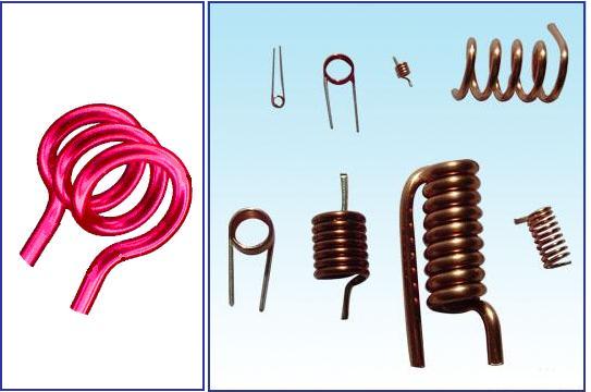
My discussion here is very simple,unlike presenting u all the history like Wikipedia. and boring you with all its properties characteristics etc. i shall leave here a simple discussion which is very much needed practically when you work them.the main emphasis here is about HOW TO DESIGN AN INDUCTOR and its COLOR CODES!!!
Sometimes you may be unable to find a particular inductor the market. This is actually a problem faced by most of the electronic hobbyists and the problem becomes more serious if your project is RF related. The inductors required for RF circuits (antenna, tuner, amplifier etc) are almost impossible to find in the market and the only solution is nothing other than home-brewing them.
often designing inductor,we generally go with solenoid which is best suited and easy made.
With a little practice and patience you can construct almost all air cored inductors at home. The inductance of an air cored inductor can be represented using the simplified formula shown below and to calculate the inductance of an air-core inductor, the same equation may be used.
- �d� is the diameter of the coil from one wire centre to another wire centre. It should be specifies in inches.
- �l� is the length of the coil specified in inches.
- �n� is the number of turns.
Notes :
- The length of the coil used in the inductor should be equal to or 0.4 times the diameter of the coil.
- As shown in the equation, inductance of the air-core inductor varies as the square of the number of turns. Thus the value �l� is multiplied four times if the value of �n� is doubled. The value of �l� is multiplied by two if the value of �n� is increased up to 40%.
Winding the coil.
- The coil must be first wounded on a plastic former of the adequate diameter (equal to the required core diameter).
- The winding must be tight and adjacent turns must be as close as possible.
- After the winding is complete, slowly withdraw the core without disturbing the coil.
- Now apply a thin layer of epoxy over the coil surface for mechanical support.
- Remove the insulation from the coil ends.
Example
Suppose you want to make an inductor which produces an inductance of 10 �H. The diameter of the coil is 1 inch and the coil length is given by 1.25 inches. You will have to find the number of turns of the coil.
Thus substituting the values in the above equation t
L = 10 inches
d = 1inch
l = 1.25 inches
n = v{L [18d * 40l]} / d = 26
Thus, the number of turns of the coil will be 26.
Number of turns/inch = 20.8
NOTE:for guys designing fm transmitters first wind 8-10 turns on a pencil (whose diameter 1/4 inches is just enough to produce required inductance for fm band).the wire may be 24 swg.for more details just mail i will provide u the details!!
those guys who cant do all these just try the softwares RFCALC or RFSIM99(links given below) this would really help you out.these softwares readily calculate and give you the dimensions you must wind,to get required inductance values.
http://sourceforge.net/projects/rfcalc/
while using these softwares you need inches to millimeter conversion some times,when circuit needed dimensions are specified in mm for that just calculate using standard conversion

SOURCE:www.circuitstoday.com&www.elexp.com


0 comments:
Post a Comment