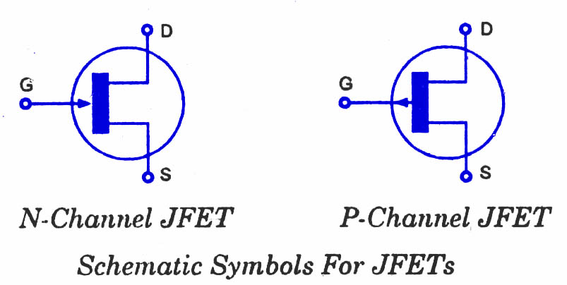
INTRODUCTION:- The JFET gate is sometimes drawn in the middle of the channel (instead of at the drain or source electrode as in these examples). This symmetry suggests that "drain" and "source" are interchangeable, so the symbol should be used only for those JFETs where they are indeed interchangeable (which is not true of all JFETs). Officially, the style of the symbol should show the component inside a circle (representing the envelope of a discrete device). This is true in both the US and Europe. The symbol is usually drawn without the circle when drawing schematics of integrated circuits. More recently, the symbol is often drawn without its circle even for discrete devices.
Tuesday, January 11, 2011
JFET
The junction gate field-effect transistor (JFET or JUGFET) is the simplest type of field effect transister. It can be used as an electrically-controlled switch or as a voltage-controlled resistance . electric charge flowflows through a semiconducting channel between "source" and "drain" terminals. By applying a bias voltage to a "gate" terminal, the channel is "pinched", so that the electric current is impeded or switched off completely.
Structure:-
The JFET is a long channel of semiconductor material, doped to contain an abundance of positive charge carriers (p-type), or of negative carriers (n-type). Contacts at each end form the source and drain. The gate (control) terminal has doping opposite to that of the channel, which it surrounds, so that there is a P-N junction at the interface. Terminals to connect with the outside are usually made ohmic.
Function:-
JFET operation is like that of a garden hose. The flow of water through a hose can be controlled by squeezing it to reduce the cross section; the flow of electric charge through a JFET is controlled by constricting the current-carrying channel. The current depends also on the electric field between source and drain.
Symbols:-


0 comments:
Post a Comment